
The right fiber laser cutting machine is defined by the work it has to perform, not by the highest power figure or the lowest quotation. To understand how to choose a fiber laser cutting machine, match its machine type, power, working area or tube capacity, and automation to the materials, thicknesses, and volumes your shop actually processes.
This guide walks through that decision step by step: production requirements, machine type, power, table or tube capacity, system components, workshop preparation, and supplier support. It also distinguishes the machine's maximum cutting capability from its repeatable production capability - a distinction that affects almost every decision that follows.
If you first need to understand the source, cutting head, motion system, and assist-gas process, see how a fiber laser cutting machine works.
Start With Your Production Requirements
Every later decision in this guide - machine type, power, table format, automation - is derived from a written production profile. Rather than specifying a machine around one unusual job, review representative work from the last 6–12 months and record it in detail before requesting a quotation.
Materials, Grades, and Thickness Range
For each material-and-thickness group in your order book or planned product range, record:
- Material, grade and surface condition. Specify the metal type and exact grade. If your stock has a coating or protective film, tell the supplier. Use the same material and surface condition for demonstration cuts as you intend to process in production.
- Usual thickness range and thickest regular job. These define the range to test for repeatable cutting speed and the finish your parts require.
- Occasional maximum thickness and frequency. Record exceptional jobs separately so the supplier can price the extra capability they require.
- Share of parts in each group. This identifies the materials and thicknesses to prioritise in sample cuts and production-cost comparisons.
Illustrative order mix by part count; add the actual grades and surface conditions to your own profile:
| Material / order group | Thickness | Share of parts |
|---|---|---|
| Carbon steel | 1–3 mm | 80% |
| Stainless steel | 4–6 mm | 15% |
| Carbon steel, occasional orders | 10–12 mm | 5% |
In this example, start the supplier's demonstration with the first two groups, which account for 95% of parts. Test the thicker 5% separately and compare the cost of the required configuration upgrade with the value of those orders and the cost of subcontracting them. Use measured job times later to determine how much production capacity each group actually needs.
Part, Sheet, Tube, and Profile Dimensions
Record both the size of the stock you buy and the dimensions of the parts you need to produce:
| For sheet metal | For tubes and profiles |
|---|---|
| Purchased sheet format | Profile shape and cross-section dimensions |
| Largest recurring part | Stock length and wall thickness |
| Typical nesting layout | Workpiece weight |
| Loading and unloading method | Acceptable remnant (tail) length |
If you regularly buy 4000 × 2000 mm sheets, a 3000 × 1500 mm machine cannot accept them whole: you would need smaller stock or preliminary sheet cutting. A machine with a matching working area, such as the Wattsan 2040 HARD, is worth evaluating to eliminate that preparation step.
If your supplier delivers tubes in 9 m lengths, specify that loading requirement before comparing machines. The Wattsan Core Pro is available with 6, 9 or 12 m loading lengths, depending on configuration. A version that accepts your stock length can avoid preliminary shortening; its profile-size and workpiece-weight limits must also match the tubes you intend to process.
The chuck system determines how close to the end of a tube the machine can cut. The chucks must retain enough material to hold and position the tube, while leaving clearance for the cutting head. Once the remaining end can no longer be securely held and reached, it becomes an unprocessable tail. A shorter minimum tail can therefore leave room for an additional part.
For example, the Wattsan Core Pro specifies a minimum tail length of 90 mm. Consider a 6000 mm tube and parts that each require 580 mm, including the cutting allowance:
| Minimum unprocessable tail | Calculated parts per tube |
|---|---|
| 500 mm - illustrative alternative | 9 |
| 90 mm - Core Pro specification | 10 |
Ten parts occupy 5800 mm, leaving 200 mm - enough for a 90 mm minimum tail, but insufficient for a machine requiring 500 mm. Across 100 tubes, that difference could yield 100 additional parts from the same stock quantity.
Before purchasing, a demonstration using your tube specification and part drawing is a useful way to see how many finished parts the machine produces and what remains. Virmer can arrange this demonstration as part of the machine-selection process.
Required Cut Quality and Downstream Operations
Define the condition in which parts must leave the cutting process: ready for assembly, ready for bending or welding, or requiring further finishing. This determines which cutting results are acceptable and how much additional work each machine configuration would leave your team.
| Requirement | What to check | How it affects your choice |
|---|---|---|
| Dimensions and fit | Check dimensions and hole positions against the drawing, and assemble mating parts. | Shows whether the machine can produce parts that fit together without adjustment. |
| Edge condition and required finishing | Check metal deposits, roughness and oxides, and whether they need removing before the next operation. | Shows how much manual work remains after cutting and how it affects the cost of making the parts. |
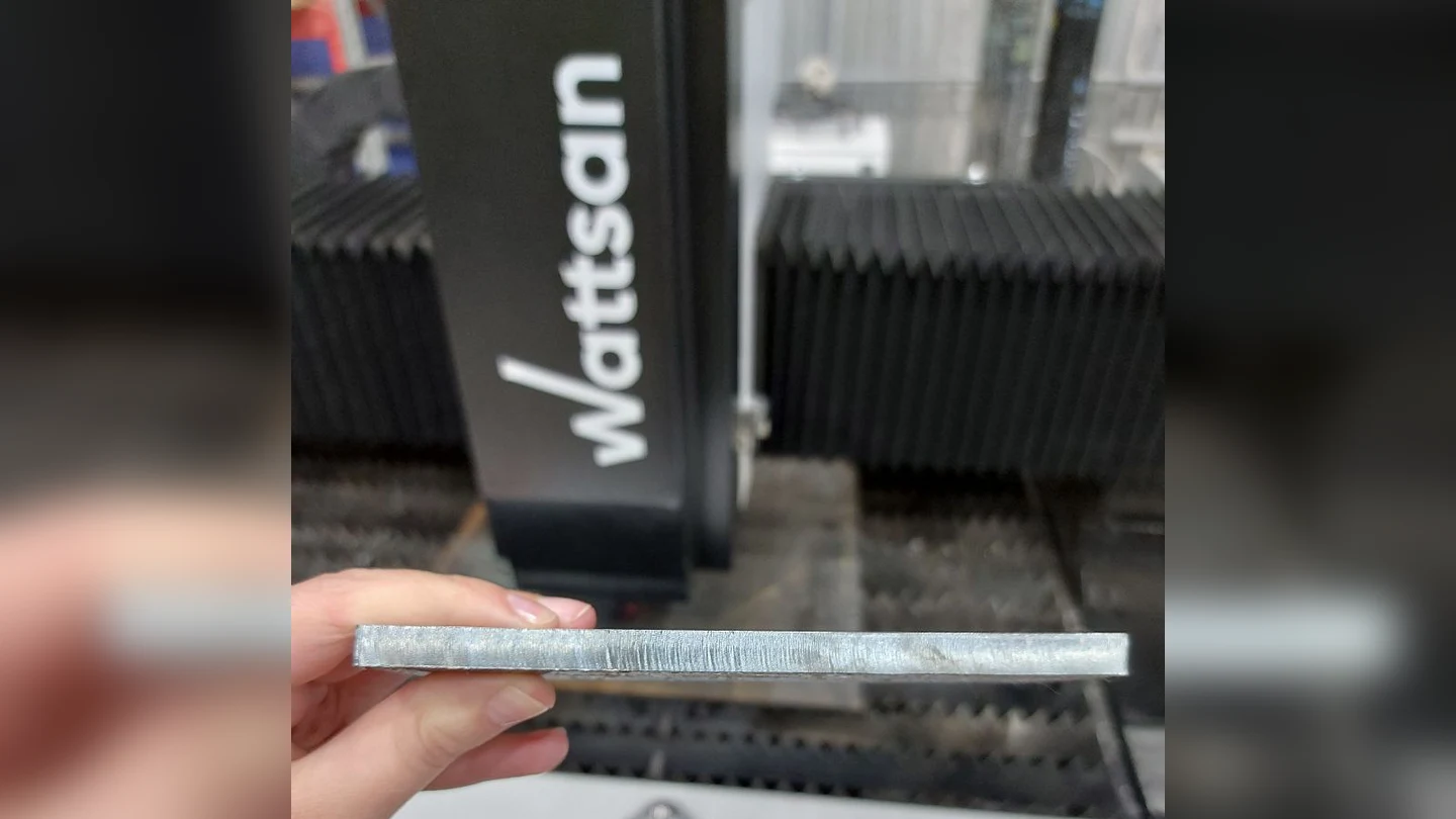
Close-up of a cut metal edge in front of a Wattsan laser cutting machine.
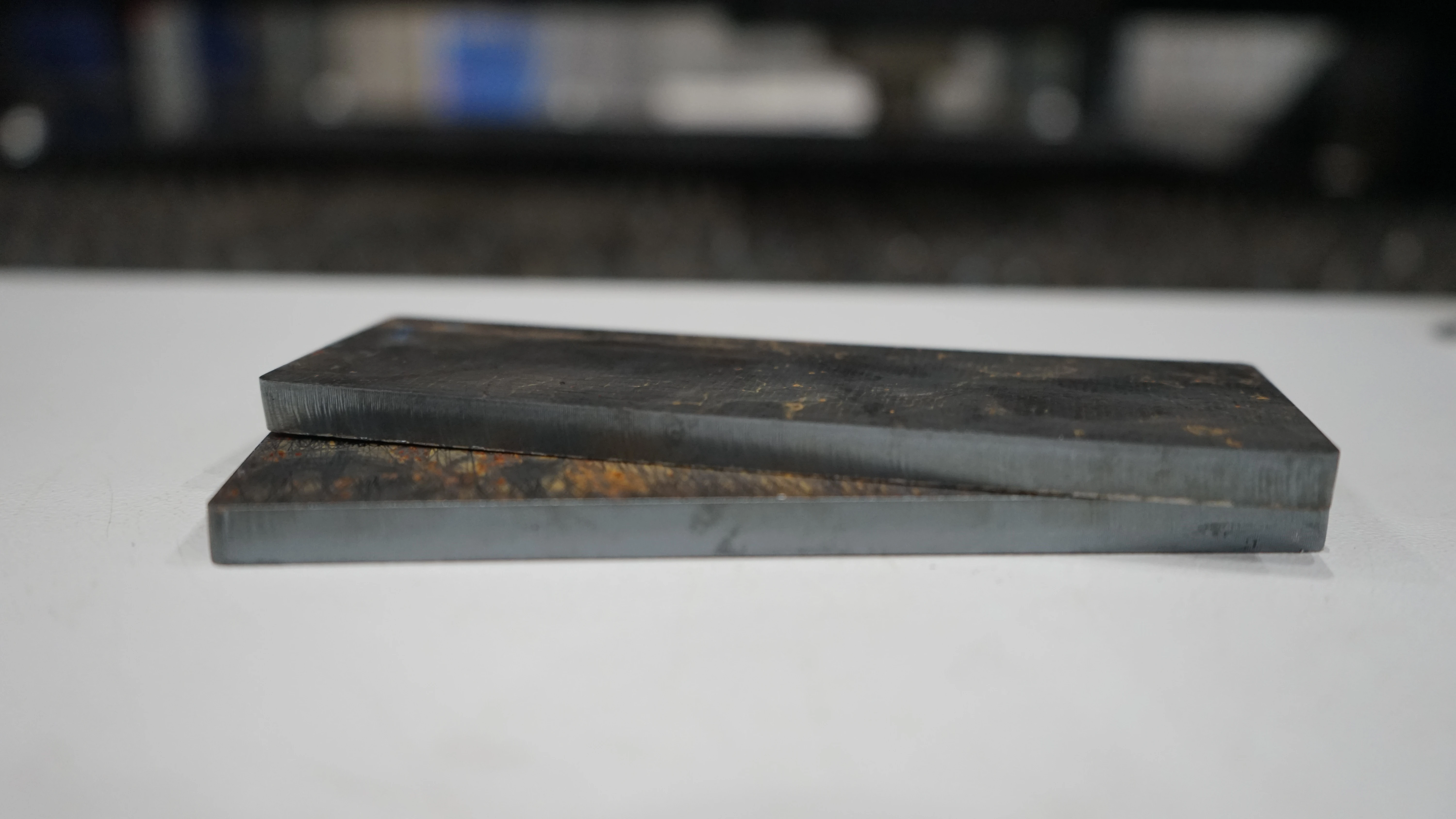
Two metal plate samples showing the cut edges produced by Wattsan fiber laser cutting machines.
For example, 200 parts requiring 1.5 minutes of cleaning each add 5 hours of manual work after cutting. A faster machine may therefore offer little overall saving if every part needs additional finishing.
For a meaningful comparison, have suppliers cut your drawing to its specified tolerances and show the parts before manual finishing. You can then see what additional work is needed before bending, welding, coating or assembly.
At equivalent source power and comparable optics, gas and settings, Wattsan A, E and S machines can achieve comparable edge finishes. For repeated production, the Wattsan 1530 S combines a rigid frame with source options up to 12 kW. It is worth considering when you need both faster cutting and consistent part dimensions across batches.
Production Volume and Workflow
Build a representative order using recurring or planned drawings, material specifications and quantities. Set the required output per shift and the production hours available after planned breaks and maintenance.
| Production requirement | Calculated example |
|---|---|
| Required acceptable parts | 200 |
| Available production time | 7 hours / 420 minutes |
| Maximum average time per acceptable part | 420 ÷ 200 = 2.1 minutes / 2 minutes 6 seconds |
This is an average across the batch, including setup, cutting, loading, unloading and material changes. Several parts may be cut from one sheet; individual cutting times do not need to equal this average.
Test the complete order with your usual holes and contours, operator count and handling equipment. Measure elapsed batch time so overlapping operations are counted once. For example, completing the 200 acceptable parts in 360 minutes leaves 60 minutes of reserve within the seven-hour window.
For recurring sheet-metal orders, the Wattsan 1530 TABLECHANGE combines a 1500 × 3000 mm working area, source options up to 12 kW and exchange tables. Higher source power can shorten cutting time on suitable jobs, while the second table lets the operator prepare the next sheet during cutting, reducing waiting between layouts.
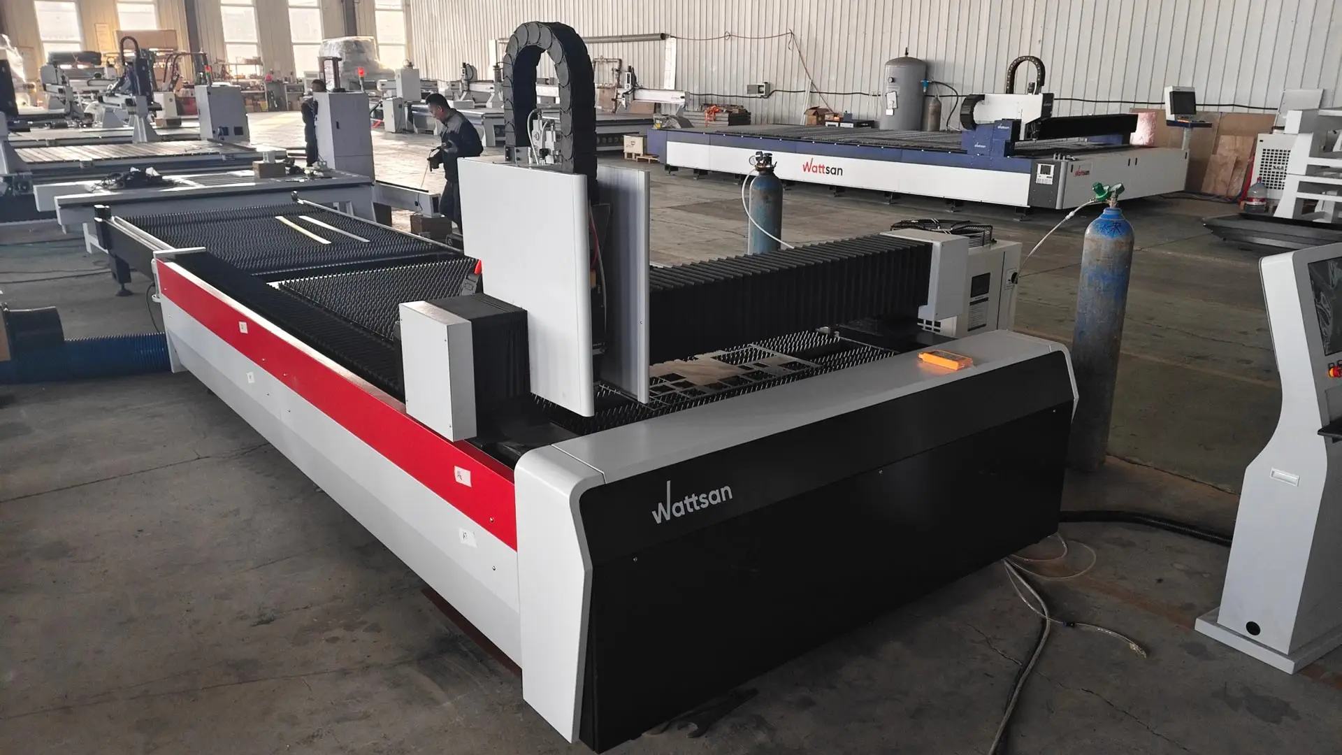
Virmer can arrange a Wattsan configuration tailored to your workload, including source power, working area, loading arrangements and automation. This allows the configuration to address the operation limiting your output and accommodate growth supported by realistic order forecasts.
Choose the Right Type of Fiber Laser Cutting Machine
Choose a flat-sheet, sheet-and-tube or dedicated tube machine according to the stock you process and whether sheet and tube orders need separate production capacity.
Flat-Sheet Fiber Laser Cutting Machines
Choose a dedicated flat-sheet machine when sheet and plate parts account for most of your work. For rare tube orders, compare subcontracting with the cost of adding tube-cutting capability.
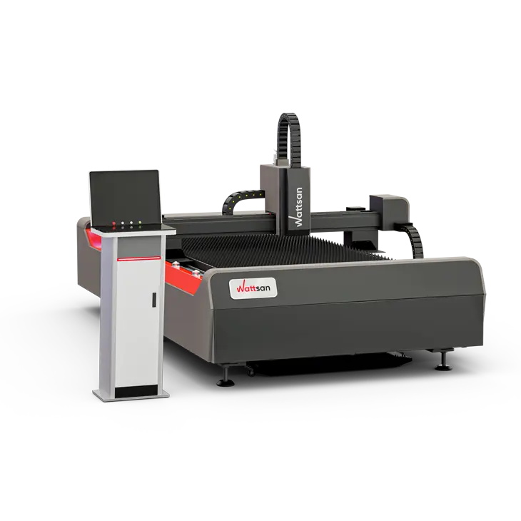
Browse fiber laser cutting machines for sheet metal
Sheet-and-Tube Combination Machines
Choose a sheet-and-tube combination when both job types recur and one installation can complete them within your production schedule. They usually share one laser source, so allow for sequential processing and the time needed to switch between operations.
Check that the tube module can perform your required cuts. A rotary attachment may have fewer loading, support or bevel-cutting options than a dedicated tube cutter.
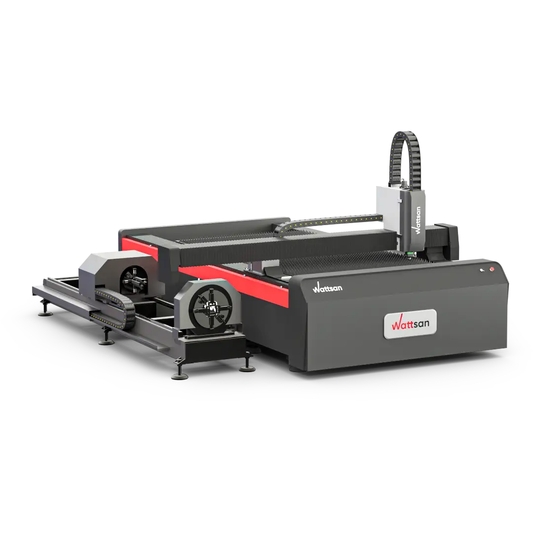
Explore sheet-and-tube fiber laser cutting machines
Dedicated Tube and Profile Laser Cutters
Choose a dedicated tube and profile cutter when tube orders need their own production capacity or require loading, support or cutting capabilities unavailable on a combination machine. Separate sheet and tube machines also let both job types run in parallel, provided you have the operators and handling capacity for both.
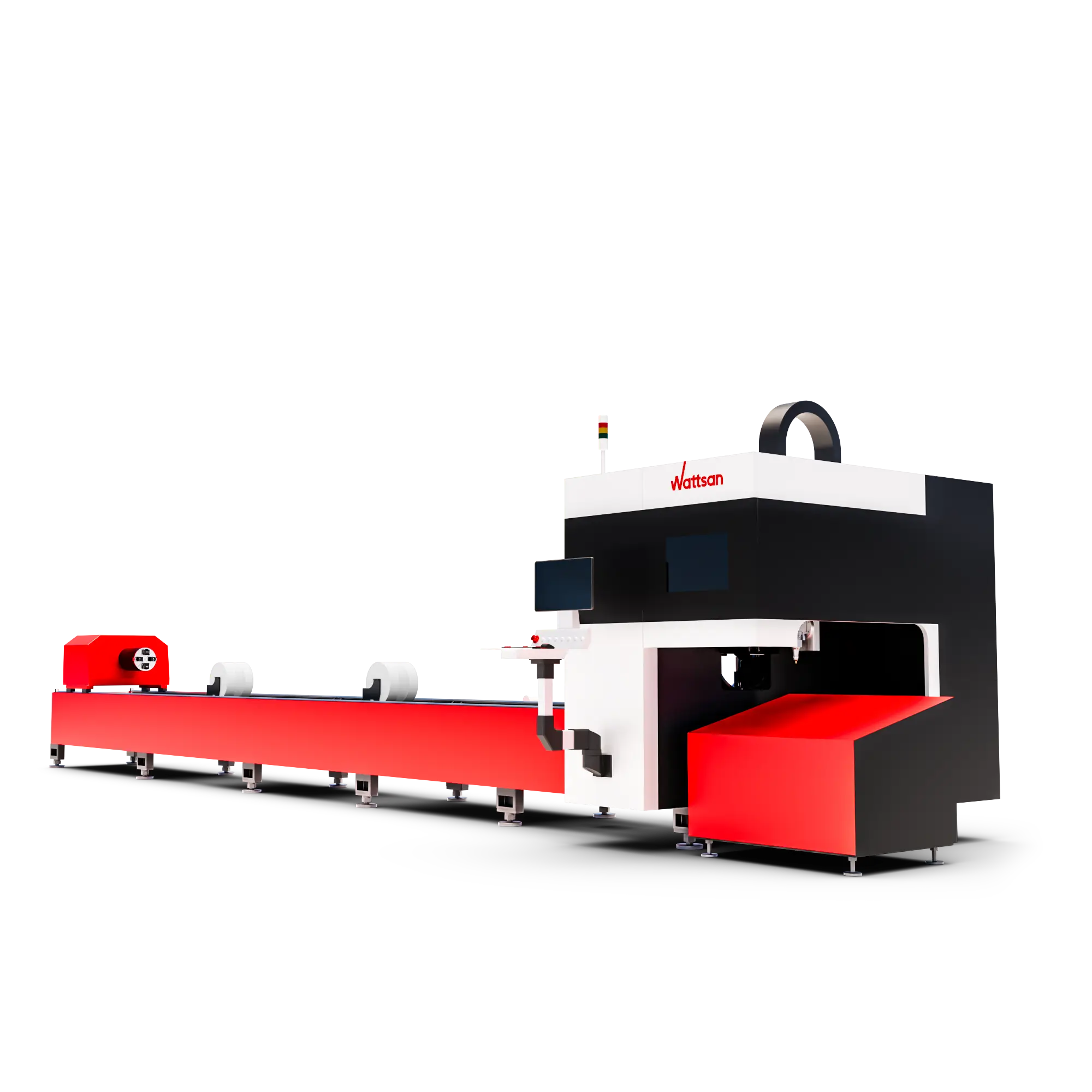
Explore dedicated laser tube and profile cutters
How To Choose Fiber Laser Cutting Machine Power ?
Choose fiber laser power for the materials and thicknesses you cut regularly, at the speed and edge quality your orders require. A machine's maximum cutting thickness shows what it can cut under stated conditions; it does not tell you how quickly or economically it will produce those parts every day.
Compare power options on the same material and drawing. Higher power is worth the additional cost when the resulting time saving increases your usable output or reduces the cost per finished part. For thin parts with many small holes or short contours, piercing and machine motion can limit the gain from a more powerful source.
Power-Selection Framework
| Material | Gas | Thickness (mm) |
1 kW (m/min) |
1.5 kW (m/min) |
3 kW (m/min) |
6 kW (m/min) |
12 kW (m/min) |
|---|---|---|---|---|---|---|---|
| Carbon steel | N2 / air | 1 | 10 | 20 | 35 | 45 | 50-80 |
| Carbon steel | N2 / air | 3 | - | - | - | 14 | 30-38 |
| Carbon steel | N2 / air | 6 | - | - | - | 5 | 10-13 |
| Carbon steel | N2 / air | 10 | - | - | - | - | 5-6.5 |
| Carbon steel | O2 | 3 | 3 | 3.6 | 4 | 3.6-4.2 | - |
| Carbon steel | O2 | 6 | 1.5 | 1.4 | 2.7 | 2.7-3.2 | - |
| Carbon steel | O2 | 10 | - | 1 | 1.5 | 2.0-2.3 | 2.3 |
| Carbon steel | O2 | 20 | - | - | 0.6 | 0.6-0.7 | 1.4 |
| Stainless steel | N2 | 1 | 13 | 20 | 45 | 60 | 63 |
| Stainless steel | N2 | 3 | 3 | 4.5 | 10 | 18 | 33 |
| Stainless steel | N2 | 6 | - | - | 2.7 | 5 | 15 |
| Stainless steel | N2 | 10 | - | - | - | 2 | 7.5 |
| Stainless steel | N2 | 20 | - | - | - | - | 1.45 |
| Aluminium alloy | N2 | 1 | 10 | 18 | 30 | 50 | 45 |
| Aluminium alloy | N2 | 3 | 1.5 | 2.5 | 8 | 16 | 25 |
| Aluminium alloy | N2 | 6 | - | - | 2 | 4 | 11 |
| Aluminium alloy | N2 | 10 | - | - | - | 1.2 | 5 |
| Aluminium alloy | N2 | 20 | - | - | - | - | 1 |
| Brass | N2 | 1 | 9 | 15 | 28 | 40 | 40 |
| Brass | N2 | 3 | - | - | 6 | 14 | 22 |
| Brass | N2 | 6 | - | - | - | 3.8 | 10 |
| Brass | N2 | 10 | - | - | - | 1 | 5 |
Columns show rated source power; some oxygen settings use reduced output. N2 means nitrogen; O2 means oxygen. Trial settings are excluded. A dash indicates no selected reference for that material, thickness and gas, not a cutting limit.
For 1 mm stainless steel with nitrogen, the 6 and 12 kW reference speeds are 60 and 63 m/min. At 10 mm, they are 2 and 7.5 m/min. A calculated 20 m of contours in 10 mm stainless steel therefore takes 10 minutes versus 2 minutes 40 seconds of cutting movement - a saving of 7 minutes 20 seconds. Complete job times also include piercing, acceleration and handling.
For copper, the 12 kW reference gives 5 m/min on 6 mm material using oxygen.
What Size Fiber Laser Cutting Machine Do You Need?
Compare the machine's usable work area and handling limits with the production requirements you recorded earlier.
What Working Area Do You Need for Cutting Sheet Metal?
- Usable working area. Compare the specified cutting length and width with the sheet formats and layouts you plan to run. Use the working-area dimensions rather than the model number.
- Table load. Confirm the permitted load per table. A 1500 × 3000 × 10 mm carbon-steel sheet weighs approximately 353 kg, before fixtures or other additional loads. The table must accommodate the complete load you intend to place on it.
Installation space: a planning example. Laser metal cutter Wattsan 1530 TABLECHANGE has a 1500 × 3000 mm working area but an overall length and width of 7.68 × 2.16 m. For an initial layout, allowing 1.3 m at the left and rear and 1 m on the other sides gives a machine-and-access zone of about 10 × 4.5 m (45 m²). Add space for the chiller, extraction equipment and sheet loading or storage; confirm the complete arrangement against the supplier's installation drawing.
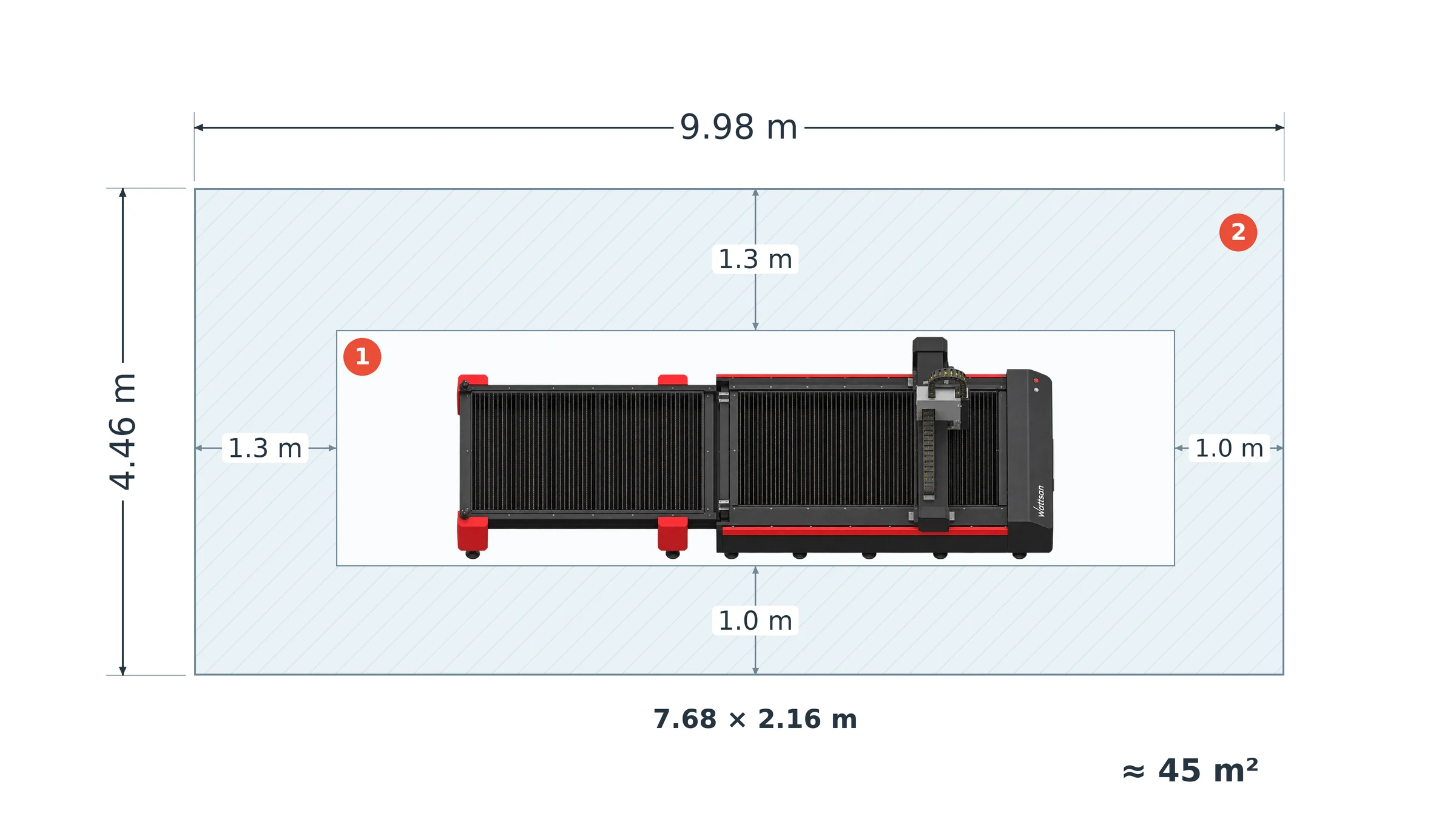
1 - Machine envelope; 2 - access clearances.
What Capacity Do You Need for Tubes and Profiles?
- Section limits. Check the supported dimensions for each profile shape you use. The chuck diameter alone does not establish the maximum workpiece size for every shape.
- Loading and finished-part length. Check raw-stock loading length and finished-part unloading length separately. Loading a long tube does not establish that a finished part of the same length can be supported and removed.
- Weight and support. Confirm whether capacity is stated per tube or per metre, and whether the supplied supports and loader cover your stock. Use the ratings for the same proposed configuration rather than combining maximum values from different variants.
Single Table, Exchange Table, or Automated Loading?
Choose the table and material-handling system by how much loading and unloading interrupt cutting and how much operator time they require.
- Single table. The laser stops while finished parts are removed and the next sheet is loaded. This can be sufficient when those pauses still leave enough time to complete your orders; additional handling equipment would add cost without solving an output constraint.
- Exchange tables. One table is prepared outside the cutting area while the other is in use. Choose this arrangement when sheet changes cause delays and the operator can prepare the next table during the cut. The Wattsan 1530 TABLECHANGE CABIN is an example of this configuration; sheet loading and unloading can still be manual.
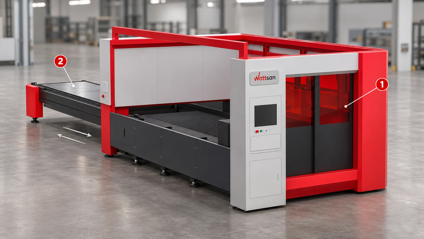
Wattsan 1530 TABLECHANGE CABIN: 1 - enclosed cutting zone; 2 - external exchange table for unloading parts and preparing the next sheet. Arrows indicate table travel. Illustrative rendering.
- Automatic loading and unloading. A sheet loader transfers stock from a stack to the machine, typically using vacuum grippers. Unloading and part sorting require the corresponding equipment. These systems are available for sheet-metal lasers as well as material-specific tube-handling systems. Consider them when moving sheets consumes substantial operator time or staffing limits the shifts you can run.
Worked cycle-time example. Assume cutting takes 20 minutes per sheet and removing parts and loading the next sheet takes 5 minutes:
- Single table: 20 + 5 = 25 minutes per repeated cycle.
- Exchange tables: if all 5 minutes of sheet preparation happen during cutting and exchanging the tables takes 30 seconds, the repeated cycle is 20.5 minutes.
Across ten such cycles, the difference is 45 minutes. These are illustrative times, not measured results for a Wattsan machine. If preparation takes longer than the cut, some waiting remains; use the demonstrated full cycle rather than assuming every handling minute is saved.
For automatic loading, compare both operator time saved and the remaining pauses between sheets with the equipment's installed cost, maintenance and space requirements. Saving labour and increasing cutting output are separate benefits: a loader can reduce manual handling even when cutting remains the slowest operation.
Which Components Matter When Choosing a Fiber Laser Cutter?
After selecting power and working area, compare the components that affect job changeovers, accurate movement and drawing preparation.
Laser Source and Cutting Head
Name the source and cutting-head models in the quotation and use that combination for the demonstration, so the sample represents the equipment you would receive.
For frequent thickness changes, automatic focus adjustment reduces manual focus setting. Height following controls the nozzle-to-sheet gap during cutting. Compare the adjustments your operator must still make between jobs, and which collision or overheating faults trigger an automatic stop.
Frame, Gantry, and Motion System
Compare the frame's stress-relief treatment, the gantry and axis drives, and protection and lubrication of guides. Stress relief helps limit distortion from residual welding stresses; guide protection and lubrication help control contamination and wear.
For drawings with many small holes and short contours, compare acceleration and finished-part dimensions alongside job time. Repeated braking and direction changes can limit the benefit of a high maximum travel speed. Choose the motion system that shortens your job while maintaining its tolerances.
The Wattsan 1530 HARD illustrates both criteria. Its heat-treated steel bed uses 15–18 mm plates and 16–30 mm stiffeners for rigidity, with additional protection against cutting heat. In a configuration with automatic nozzle changing and camera-based nozzle inspection, it also reduces manual work between jobs requiring different nozzles and stops cutting when nozzle damage is detected. This combination is worth evaluating for production involving repeated nozzle changes and sustained cutting, where both changeover time and protection of the machine under production loads matter.
CNC, CAD/CAM, and Nesting Software
Have your future operator import one of your files, correct drawing errors, arrange the parts and export a cutting job in the supplied software. Record preparation time and manual edits to establish the work needed before cutting can start. For tube work, demonstrate the corresponding tube-programming workflow.
Compare layouts using the same sheet size, quantities, spacing and permitted part rotation. In an illustrative example, fitting 24 parts instead of 20 on the same sheet produces 20% more parts per sheet, making the benefit of nesting measurable in material use.
What Does Your Workshop Need to Run a Fiber Laser Cutter?
Before ordering, obtain installation requirements for the complete machine and its auxiliary equipment. Use them to identify upgrades needed in your workshop before delivery.
| Requirement to confirm | What it tells you |
|---|---|
| Electrical supply: voltage, phase, total connected load, earthing and supply stability for the complete installation. | Whether your existing electrical connection is sufficient or needs upgrading before delivery. |
| Assist gas: type, pressure, peak flow and purity for your regular materials and thicknesses. | Which supply arrangement suits the cutting process: cylinders, bulk storage or on-site generation. |
| Compressed air: required pressure, delivered flow, dryness and filtration. | Whether your compressor, dryer and filters can serve the laser or need upgrading. |
| Cooling: chiller capacity, water specification and permitted ambient temperature range. | Whether the cooling package suits the selected source and your workshop conditions. |
| Extraction: required airflow, filtration, ducting and discharge location. | What extraction equipment and ductwork must be installed before production starts. |
| Site and delivery: floor loading, flatness, anchoring, access openings and unloading arrangements. | Whether the floor and delivery route need preparation, and which lifting equipment is required. |
Evaluate the Supplier, Warranty, Training, and Support
Compare the support included in the offer for startup, maintenance and repairs.
Warranty coverage. Check the warranty terms for the machine, source and head, including parts, labour, travel and return shipping. Establish who handles each claim and which exclusions apply, so you can distinguish covered repairs from costs you would pay.
Service and spare parts. Agree the route for remote diagnosis, engineer visits and replacement parts, including support after the warranty expires. Confirm stock locations and lead times for critical components so you can plan repairs and any interruption to production.
Commissioning and training. Virmer provides engineer-led commissioning and operator training to help bring your machine into production. Its engineers can assist with initial setup and test production on your materials, while on-site or remote training covers machine operation and maintenance. This helps your team learn how to prepare jobs, run the equipment and carry out routine care after handover.
Virmer also checks each machine at the Wattsan factory, at its Netherlands warehouse and before customer dispatch. Wattsan owners receive lifetime online technical support.
Best Fiber Laser Cutting Machines for Sheet Metal and Tubes
Our Wattsan shortlist below matches the production brief developed above to models available from Virmer.
| Production task | Recommended Wattsan models | Specifications that match the task |
|---|---|---|
| Small blanks in a space-limited workshop | Wattsan 1313 A Cabin Wattsan 1309 Mini |
1300 × 1300 mm; up to 6 kW; enclosed cabin. Machine envelope: 2545 × 2834 mm. |
| General sheet-metal and stainless-steel job-shop work | Wattsan 1530 A Wattsan 1530 S |
Both: 1500 × 3000 mm. 1530 A: up to 6 kW. 1530 S: up to 12 kW, for a higher-power source in the same sheet format. |
| Consecutive layouts with frequent sheet replacement | Wattsan 1530 TABLECHANGE CABIN | 1500 × 3000 mm; up to 12 kW; protective cabin and automatic exchange tables. |
| Sheet parts and tube components on one machine | Wattsan 1530 ROTARY | 1500 × 3000 mm; up to 12 kW. Tube module: round 10–220 mm; square 10–140 mm. |
| Higher-power sheet/plate cutting | Wattsan 1530 HARD Wattsan 2040 HARD |
Up to 30 kW. 1530 HARD: 1500 × 3000 mm. 2040 HARD: 4000 × 2000 mm. |
| Dedicated tube and profile production | Wattsan Core Pro | 1.5–30 kW; 6, 9 or 12 m loading versions; workpiece-weight versions of 140, 400 or 1500 kg; pneumatic tube supports. |
| Heavy tubes and beveled weld preparations | Wattsan Nova | 15–30 kW; workpieces up to 3000 kg; automatic feeding and a swivel head for bevels up to 45°. |
Send your drawings, material specifications and required output to Virmer at info@virmer.com. Our specialists can recommend a Wattsan configuration, arrange a demonstration on your materials and prepare an itemised quotation. This gives you a machine proposal matched to your production requirements, with the included equipment and services clearly identified.
Frequently Asked Questions About Fiber Laser Cutting Machine Choosing
How much does a fiber laser cutting machine cost?
Purchase price depends on power, working area, table architecture, enclosure, tube capability, automation, source/head configuration, auxiliary equipment, delivery, commissioning, and support. There is no universal price - request a configuration-specific quotation and distinguish the initial figure from the complete installed project cost.
What does a fiber laser cutting machine cost to run?
Running costs include electricity, assist gas, consumables, labour, software, filters, planned maintenance, and downtime. These vary by machine, material mix, and utilisation, so treat any hourly-cost figure as an estimate to validate against your own process rather than a fixed rate.

