
A fiber laser cutting machine is a CNC-controlled system that directs a high-power beam from a fiber laser source through a cutting head, focuses it onto metal, and uses assist gas to remove the molten material while the head follows a programmed cutting path. The source generates the beam, but the source alone is not the machine: delivery optics, motion control, gas supply, cooling, and safety systems all have to work together for the process to cut a usable part.
This article explains the laser cutting principle by following the complete fiber laser cutting process, from a digital drawing to a finished metal part - what the machine contains, how its subsystems relate to each other, and how the process unfolds step by step. For the physics of how the beam itself is generated inside the source, see how a fiber laser generates and amplifies light.
What Is a Fiber Laser Cutting Machine?
A fiber laser cutting machine is a CNC-controlled, non-contact thermal cutting system used primarily to cut metal. It combines several distinct subsystems, each with a specific job:
- A fiber laser source generates the beam.
- A delivery or process fiber carries the completed beam to the cutting head.
- A cutting head collimates, focuses, and directs the beam while delivering assist gas.
- A motion system and CNC controller move the head or workpiece along a programmed path.
- Cooling, extraction, gas delivery, sensing, and safety systems allow the process to run reliably.
"Fiber" describes the architecture of the laser source, not the presence of a fiber-optic cable somewhere in the machine. A system qualifies as a fiber laser cutting machine when its cutting beam is generated by a fiber laser source.
In British English, the same equipment is called a fibre laser cutting machine; the spelling changes, but the technology does not.
What Are the Main Parts of a Fiber Laser Cutting Machine?
Cut quality and uptime depend on how the whole system performs together, not on laser-source wattage alone. The sections below walk through each subsystem and the role it plays in the finished result.
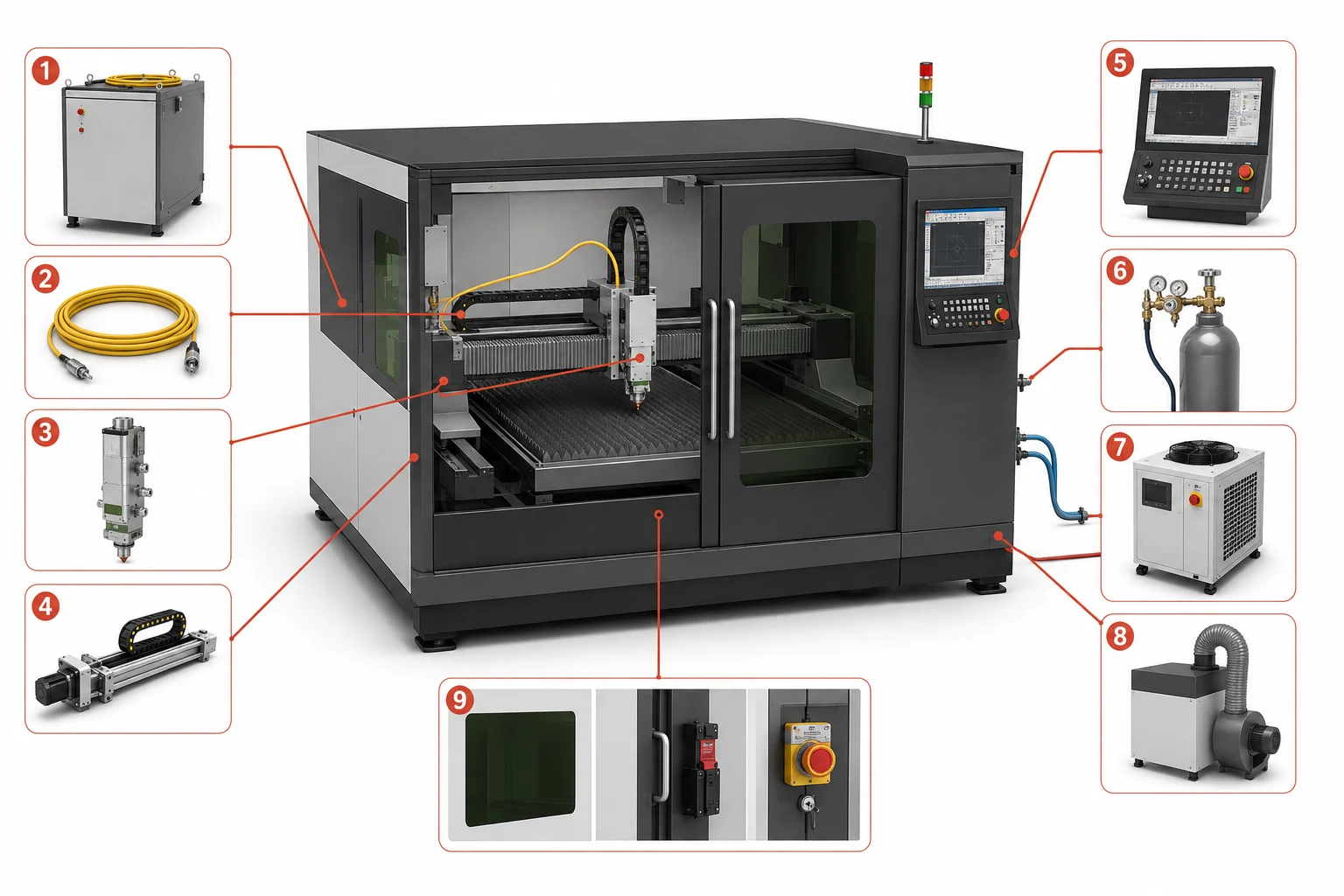
The main systems of a fiber laser cutting machine: 1 - Fiber laser source, 2 - Delivery/process fiber, 3 - Fiber laser cutting head, 4 - Gantry and motion system, 5 - CNC controller and CAD/CAM interface, 6 - Assist-gas supply system, 7 - Water chiller, 8 - Fume extraction and filtration, 9 - Protective enclosure and safety systems
Fiber Laser Source
The source converts electrical input into a controlled laser beam. Industrial sheet-metal cutters commonly use high-power continuous-wave ytterbium fiber sources, whose near-infrared wavelength and beam characteristics are well suited to many industrial metal-cutting applications. The source is one subsystem among several: it supplies the beam, while everything downstream determines how that beam is delivered, shaped, and turned into a finished cut. Readers curious about the basic physics of how lasers produce coherent light can find the underlying principle of stimulated emission explained there.
Beam Delivery Fiber
Two different fibers are involved in a fiber laser system, and it helps to keep them separate. The active doped fiber sits inside the source, where light is generated and amplified. The delivery, or process, fiber is a separate component that carries the already-generated beam from the source to the cutting head.
Because the beam travels through this largely enclosed fiber path, fiber systems avoid the long open beam-delivery route and repeated external mirror alignment found in traditional CO2 cutting systems. This does not mean a fiber laser machine contains no mirrors anywhere; some optical architectures still use reflective elements within the cutting head or beam-switching assemblies.
Fiber Laser Cutting Head
The cutting head does not generate the laser. It receives the beam from the delivery fiber, prepares it optically, maintains the required position above the workpiece, and supplies assist gas to the cutting zone. Three functional groups inside the head handle that job.
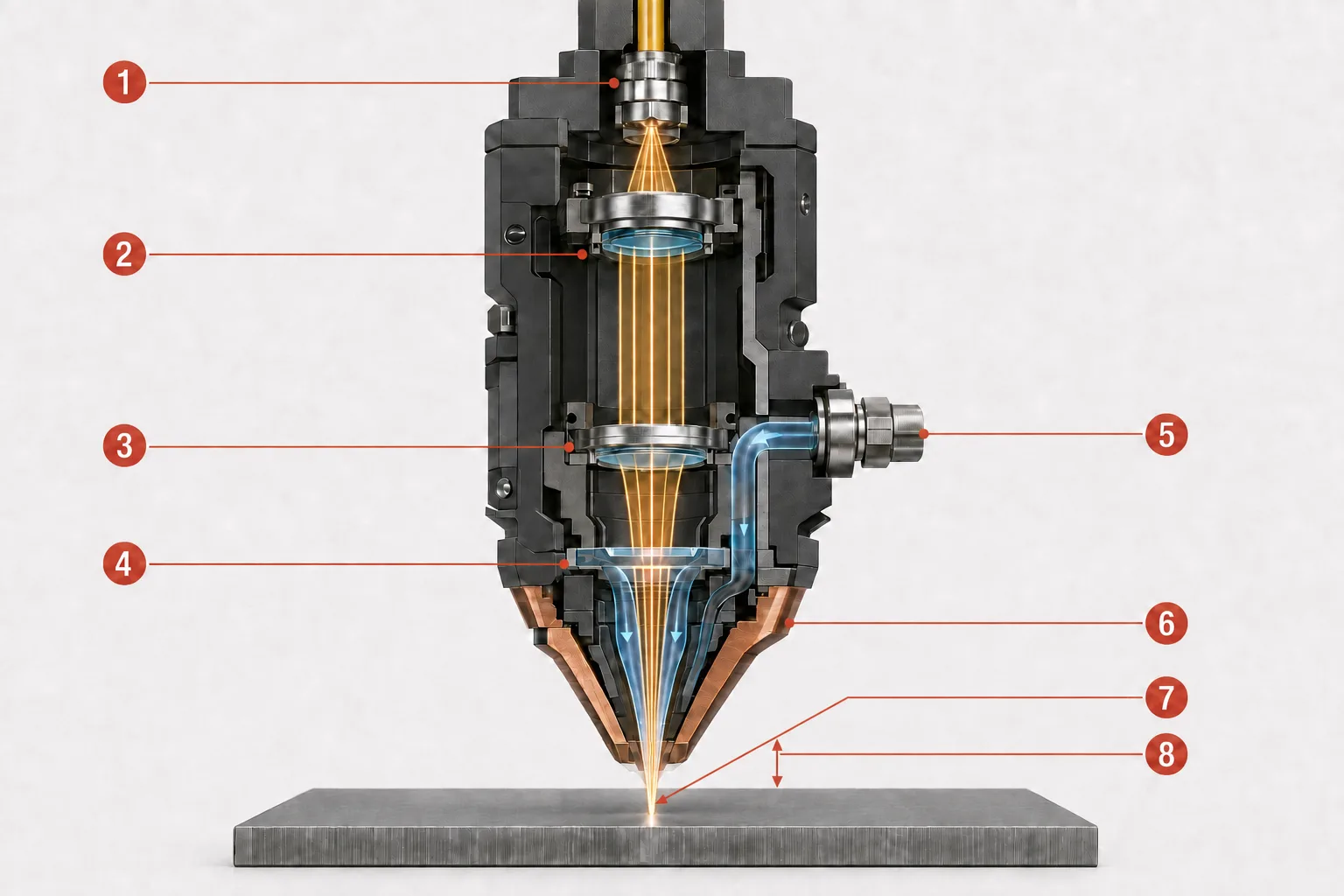
Inside a fiber laser cutting head, the delivery fiber (1) feeds the beam into the collimating optics (2), which form an approximately parallel beam. The focusing optics (3) then concentrate it through a replaceable protective window (4). Assist gas enters through the inlet (5) and flows coaxially through the nozzle (6). The beam reaches its narrowest point at the focus position (7), while the stand-off distance (8) is the physical gap between the nozzle tip and the workpiece. The focus is shown at the material surface for illustration; its actual position may be above, at or below the surface.
Beam Collimation and Focusing
The beam leaves the delivery fiber in a diverging form, is collimated into an approximately parallel beam, and is then focused into a small spot at the workpiece: diverging output from delivery fiber → collimated beam → focused spot at the workpiece.
A smaller spot concentrates energy into a smaller area and can raise power density, but final cut accuracy is not determined by spot size alone; nozzle alignment, motion accuracy, and process parameters all contribute. Think of this stage as an adjustable magnifying glass paired with a controlled gas nozzle - though unlike sunlight through glass, the machine starts with a controlled beam and uses engineered optics to position the focus precisely within a programmed process.
Focus and Height Control
Focus position refers to where the narrowest point of the beam - the beam waist - sits relative to the material surface; it may be positioned at, above, or below the surface depending on the process. An autofocus mechanism adjusts it automatically, without the operator repositioning the optical assembly by hand.
Stand-off distance is a related but separate parameter: the physical gap between the nozzle and the workpiece. A capacitive sensor detects changes associated with that distance, and the height-control system uses the signal to adjust the Z-axis, keeping the gap consistent as the head travels over minor sheet variations. Confusing focus position with stand-off distance can lead to incorrect diagnosis when a cut goes wrong.
Protective Window, Nozzle, and Assist Gas
One or more replaceable protective windows help protect the more expensive collimating and focusing optics from spatter, vapour, smoke, and other contamination; some heads use several windows along the optical path. These are consumable protective components, not the main focusing lens.
The focused beam and assist gas pass through the nozzle towards the same point on the workpiece. The nozzle shapes and directs the gas jet that clears molten material from the kerf. Nozzle diameter, condition, alignment, and distance from the workpiece all affect melt ejection - a damaged or off-centre nozzle is a common source of inconsistent edge quality.
CNC Controller and CAD/CAM Software
Four related concepts work together to turn a design into a finished part:
- CAD (computer-aided design) defines or imports the geometry of the part.
- CAM/nesting software positions parts on the sheet, creates toolpaths, and assigns process rules.
- The CNC (computer numerical control) controller converts the program into coordinated machine motion and process commands.
- Machine parameters include laser power, cutting speed, focus position, assist-gas selection, gas pressure, and piercing routines.
Motion System, Gantry, and Z-Axis
X/Y motion follows the programmed contour across the sheet, while the Z-axis maintains the cutting head's position relative to the workpiece. Servo drives, guides, transmission, feedback, and calibration all influence how accurately that motion is executed - a precise laser spot cannot compensate for an unstable frame or a poorly calibrated axis. Transmission design varies between designs such as rack-and-pinion and linear-motor systems; no single technology applies to every machine.
Machine Bed and Worktable
The bed provides frame and structural support. The worktable slats support the sheet while allowing molten material, sparks, and debris to fall into the collection area below. Machines may use a fixed or exchange worktable; sheet, tube, and 3D machines each use a workholding layout suited to their workpiece shape.
Assist-Gas Supply System
The machine requires a regulated gas delivery system with the correct pressure, flow, and purity for the process. Oxygen, nitrogen, and compressed air are three common assist-gas options, covered in detail later in this article.
Water Chiller
A water chiller removes heat from specific components - commonly the laser source and/or the cutting head - rather than cooling the cut itself, which is governed by the beam-material interaction. Exact cooling circuits vary by machine and source manufacturer.
Fume Extraction and Filtration
Laser cutting produces fumes, fine particles, vaporised material, and spatter. Extraction removes contaminated air from the cutting area, helping to protect operators, optics, electronics, and the wider workplace. It does not make every material or coating safe to process on its own; unfamiliar materials still need identification and appropriate filtration.
Enclosure, Interlocks, and Safety Systems
Industrial machines typically include emergency stops, warning signals, and defined safe-servicing procedures regardless of layout. Depending on its design, a machine may add a full protective enclosure or operate within a controlled laser area with other engineered safety measures. Enclosed models additionally use interlocked doors or panels, correctly rated viewing windows, and, where supplied, fire detection.
Not every enclosed machine can automatically be labelled "Class 1." Classification depends on the complete certified configuration and the accessible emission during normal operation - an enclosed system may still contain a much higher-class embedded laser, and opening the enclosure for servicing changes the hazard conditions.
How Does a Fiber Laser Cutting Machine Work? Step by Step
Fiber laser cutting machine operation depends on all the subsystems above working together in a defined sequence. The steps below present that sequence as one continuous process, from the initial design file to an inspected, separated part. The steps below present that sequence as one continuous process, from the initial design file to an inspected, separated part.
Step 1: The Design Is Prepared in CAD/CAM Software
The part geometry is imported or created in CAD, then arranged on the sheet through nesting. CAM software generates toolpaths, sets the contour order, adds lead-ins and lead-outs, and assigns process parameters for the selected material and thickness.
Step 2: The Material Is Loaded and the Job Is Set Up
The operator or an automated loading system positions the sheet, tube, or profile. The job setup then confirms material and thickness and selects validated parameters and assist gas, checking the nozzle, protective window, gas supply, cooling, extraction, and safety systems before starting.
Step 3: The Source Generates the Beam and the Delivery Fiber Carries It to the Head
Electrical power is converted into a laser beam inside the fiber source (see the dedicated fiber laser technology article for the underlying physics), and the completed beam then travels to the cutting head through the delivery fiber.
Step 4: The Cutting Head Focuses the Beam and Sets Working Distance
The head's optics collimate and focus the beam into a small working spot, while autofocus and capacitive height control set the focus position and stand-off distance as described above.
Step 5: The Laser Pierces the Metal
Before contour cutting can begin, the beam normally needs to create an initial opening in the material. Piercing can use a different power profile, focus position, gas, or timing than steady-state cutting; thicker material makes it more demanding and can generate spatter that stresses the protective window and nozzle.
Step 6: The Focused Beam Creates a Molten Cutting Zone
The material absorbs part of the beam's energy, which is concentrated into a small area. Temperature rises until the material melts and, under some conditions, partially vaporises. This forms a narrow channel called the kerf, and the surrounding material may experience a heat-affected zone. In common sheet-metal cutting, melting and melt ejection - not full vaporisation - are usually the dominant mechanisms.
Step 7: Assist Gas Removes the Molten Material
A coaxial gas jet pushes molten material through and out of the kerf. Depending on the gas used, it may also support or shield against oxidation, influence temperature and process stability, and affect dross, edge colour, and downstream processing requirements.
Step 8: CNC Motion Forms the Programmed Contour
The CNC controller coordinates the laser, cutting head, axes, gas delivery, and process timing. It may vary speed and process behaviour around corners, small holes, lead-ins, or changes in geometry, rather than following every contour at one constant speed.
Step 9: Parts Are Separated and Checked
Once cutting is complete, parts are unloaded and inspected for penetration, dross or burr, kerf width, edge roughness, taper, heat tint, and dimensional conformity. Depending on what inspection finds, operators may adjust parameters, replace the nozzle, inspect the optics, or recalibrate the machine.
What Happens Where the Laser Meets the Metal?
Cutting happens through a short sequence of physical events at the point of contact: the material absorbs the beam's energy, that energy turns into heat fast enough to melt (and partially vaporise) a narrow channel, and the resulting molten material is cleared without any tool ever touching the sheet. The three sections below follow that sequence, starting with how the metal takes in the beam's energy in the first place.
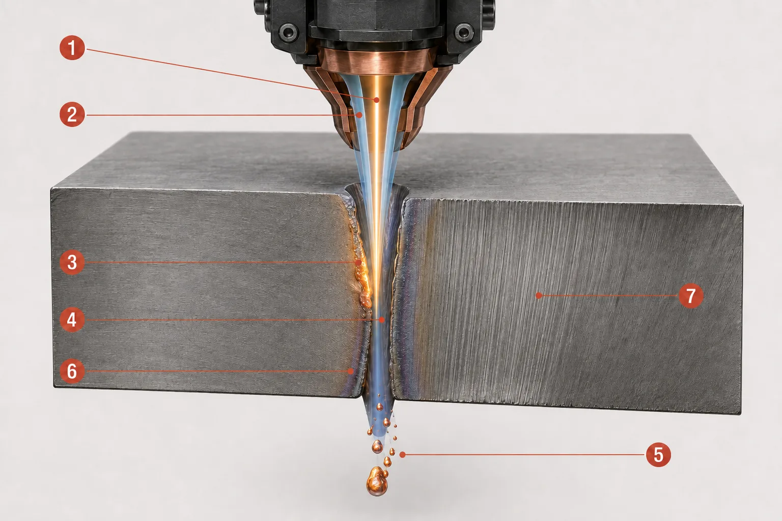
At the cutting zone, the focused laser beam (1) heats a narrow area while the coaxial assist-gas jet (2) pushes molten material downward. The molten zone (3) forms at the active cutting front and leaves a narrow channel called the kerf (4). Expelled melt (5) exits through the underside of the sheet, while a narrow heat-affected zone (6) remains beside the kerf and drag lines or striations (7) form on the cut wall. The illustration is conceptual and not shown to scale.
Absorption and Heat Transfer
Metal does not absorb all incident laser energy equally. Absorption depends on wavelength, alloy, surface condition, temperature, coatings, and oxide layers, and a surface's behaviour can change as it heats. Cutting becomes possible when energy is delivered to a small zone faster than heat can spread away from it.
Melting, Limited Vaporisation, and Kerf Formation
- Melt pool / molten zone: the localised region of material that has been heated past its melting point.
- Vaporisation: the conversion of heated material into vapour. In most sheet-metal cutting processes, it occurs only to a limited extent alongside predominantly melting.
- Kerf: the narrow channel produced when laser energy melts or removes material and assist gas clears it from the cutting path.
- Heat-affected zone (HAZ): the region of surrounding material whose properties have been altered by heat without being melted.
- Dross: re-solidified molten material adhering to the underside of the cut.
- Drag lines / striations: the fine, near-vertical marks visible on a cut edge, formed as the process moves through the material thickness.
A narrow HAZ, a burr-free edge, or a perfectly clean cut are process outcomes, not guarantees - they depend on the complete machine setup, material, and parameters.
Why the Process Is Non-Contact
No mechanical cutting tool presses against the workpiece, which reduces tool-force deformation and eliminates blade wear. Non-contact does not mean no wear or no maintenance: nozzles, protective windows, worktable slats, filters, and mechanical systems still require regular care and replacement.
How Do the Laser Beam and Assist Gas Remove Metal?
Assist gas chemistry and cutting mechanism are two sides of the same process: the gas determines what happens at the cut edge, while the mechanism describes how the beam and gas jet remove material together. The sections below connect each gas to its dominant mechanism and typical result.
Nitrogen and Fusion Cutting
Nitrogen is used as a largely inert cutting gas in fusion cutting: the beam supplies the cutting heat, while the gas jet ejects the melt mechanically rather than reacting with it. Because nitrogen shields the hot edge from air, this combination typically produces a clean, oxide-free edge, which is why it is common on stainless steel, aluminium, and other suitable metals. High pressure and flow may be required, which can make gas consumption significant.
Oxygen and Reactive Cutting
Oxygen drives reactive, or flame, cutting: it reacts with suitable hot metal, adding energy to the process through an exothermic reaction, and is commonly associated with carbon and mild steel. The resulting cut edge is oxidised, and that oxide layer may affect subsequent welding, coating, or painting. Oxygen is not automatically the fastest or best option for every metal and thickness.
Compressed-Air Cutting
Compressed air contains both nitrogen and oxygen, and it can be an economical option for suitable applications. The oxygen content contributes a limited reactive effect, so some oxidation may remain on the edge. Performance depends on pressure, flow, air quality, dryness, filtration, material, thickness, and the required edge finish. Compressed air is not a universal substitute for dedicated nitrogen or oxygen supply.
Sublimation Cutting
Sublimation cutting removes material primarily through vaporisation, with minimal melting. The principal mechanisms are fusion, reactive, and sublimation cutting, but industrial sheet-metal fiber cutters rely mainly on the first two; sublimation is more relevant to specialised, precision applications.
Cutting mechanism and laser temporal mode are different classification axes: fusion, reactive, and sublimation cutting describe how material is removed, while continuous-wave (CW), quasi-continuous-wave (QCW), and pulsed operation describe how the source emits the beam - the terms are not interchangeable.
The table below compares the three assist gases directly:
| Gas | Main role | Common use | Typical edge characteristic | Important limitation |
|---|---|---|---|---|
| Oxygen | Supports cutting through an exothermic oxidation reaction | Primarily carbon/mild steel | Oxidised edge | Oxide may need removal before downstream processing |
| Nitrogen | Ejects melt without deliberately oxidising the edge | Stainless steel, aluminium, and other suitable metals | Clean, oxide-free edge when the process is correct | Can require high pressure, flow, and gas consumption |
| Compressed air | Ejects melt with a limited oxygen-assisted contribution | Selected suitable metals and thicknesses | Some oxidation is possible | Quality depends heavily on air preparation and process requirements |
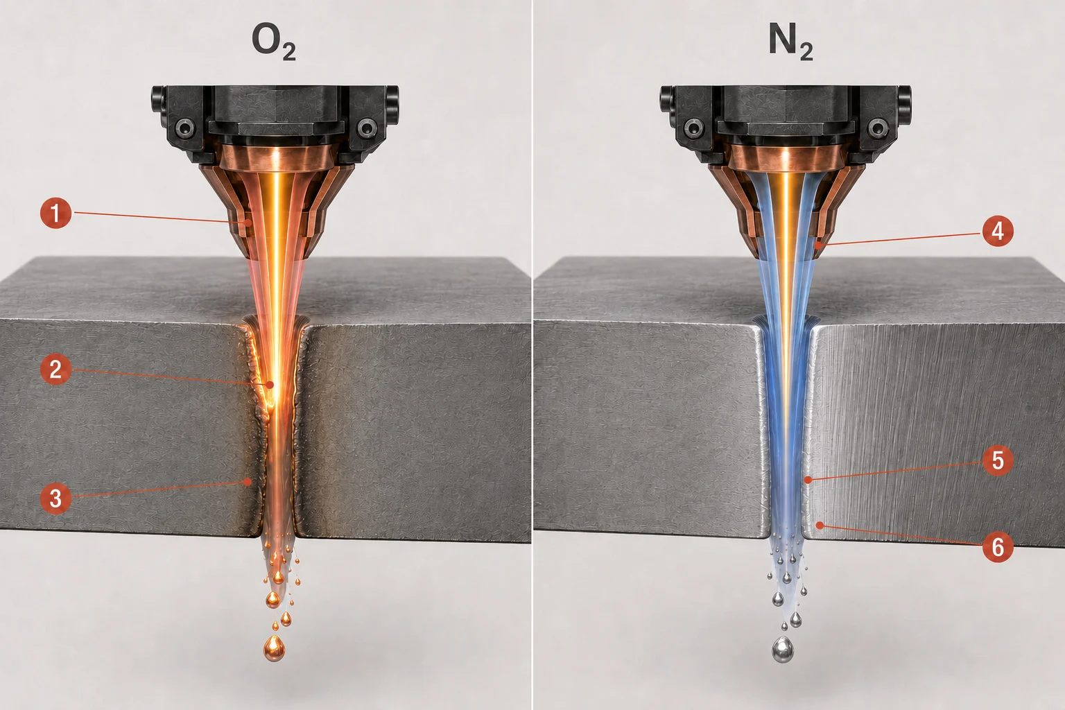
In oxygen-assisted reactive cutting, the oxygen flow (1) removes molten material while an exothermic oxidation reaction (2) adds heat to the process and leaves an oxidised cut edge (3). In nitrogen-assisted fusion cutting, the nitrogen flow (4) ejects the melt mechanically under pressure (5) and can produce a clean, non-oxidised edge (6) when the process parameters are correct. The illustration shows typical differences; actual results depend on the material, thickness and machine settings.
What Determines Cut Quality and Finished-Part Accuracy?
No single setting determines cut quality on its own. Each process parameter changes a physical condition at the cutting zone, and that condition produces a visible result on the finished edge. The table below connects the main variables - laser power, cutting speed, focus position, gas pressure and flow, nozzle alignment, stand-off distance, and material condition - to what changes physically and what a reader might see if that variable drifts off target:
| Variable | What changes physically | Possible visible result if incorrect |
|---|---|---|
| Laser power | Energy delivered to the cutting zone | Incomplete cut, overheating, wider kerf, or excessive dross |
| Cutting speed | Interaction time and energy per unit length | Lack of penetration, burn marks, rough edge, or excess heat input |
| Focus position | Spot size and energy distribution through thickness | Taper, wider kerf, roughness, or unstable penetration |
| Gas pressure/flow | Melt-ejection force and shielding/reaction behaviour | Bottom dross, oxidation, irregular kerf, or unstable cutting |
| Nozzle alignment | Coaxial relationship between beam and gas jet | Uneven edge quality depending on cutting direction |
| Stand-off distance | Gas-jet geometry and head position | Unstable process, dross, or collision risk |
| Material condition | Absorption, heat conduction, and surface reaction | Inconsistent start, roughness, spatter, or variation across the sheet |
These are possible relationships rather than a complete diagnostic chart, and the same visible defect can often trace back to more than one cause.
Kerf, Accuracy, Repeatability, and Tolerance
Beyond individual parameters, final accuracy depends on the whole system: source and beam quality, cutting-head optics, alignment, CNC interpolation, servo response, frame rigidity, calibration, gas delivery, material flatness, and the condition of consumables. Several related terms describe different aspects of this outcome and should not be treated as equivalent figures:
- Beam spot size - the diameter of the focused beam at the workpiece.
- Kerf width - the actual width of material removed during the cut, which is influenced by spot size but not identical to it.
- Machine positioning accuracy - how precisely the machine can move to a commanded position.
- Repeatability - how consistently the machine returns to the same position over multiple cycles.
- Finished-part tolerance - the allowable dimensional variation on the completed part, which reflects the combined effect of all the factors above.
What Types of Fiber Laser Cutting Machines Are There?
Fiber laser cutting machines are built in several layouts, each suited to different workpiece shapes.
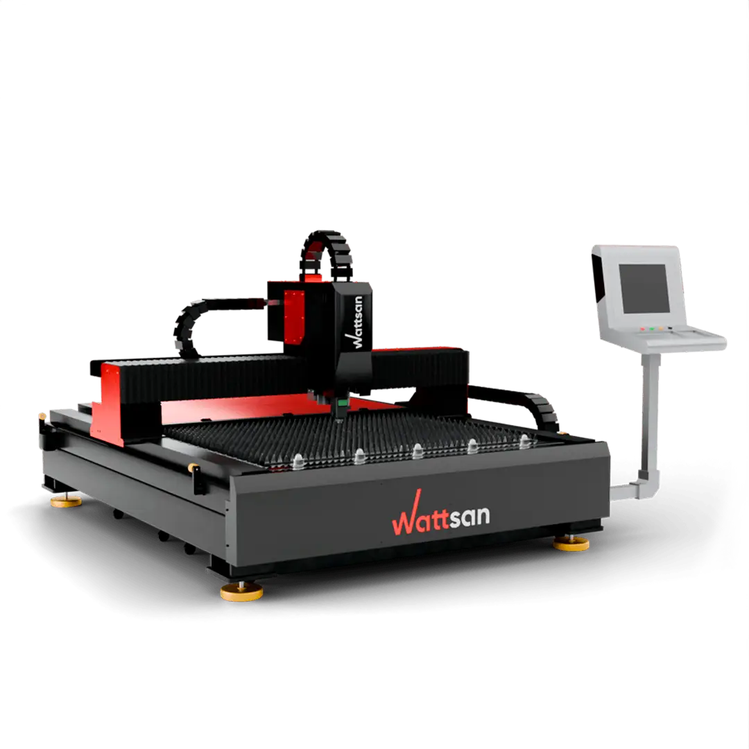
Flat-Sheet Fiber Laser Cutters
The most common layout uses a gantry moving over a fixed or exchange table, designed for cutting flat sheet and plate material.
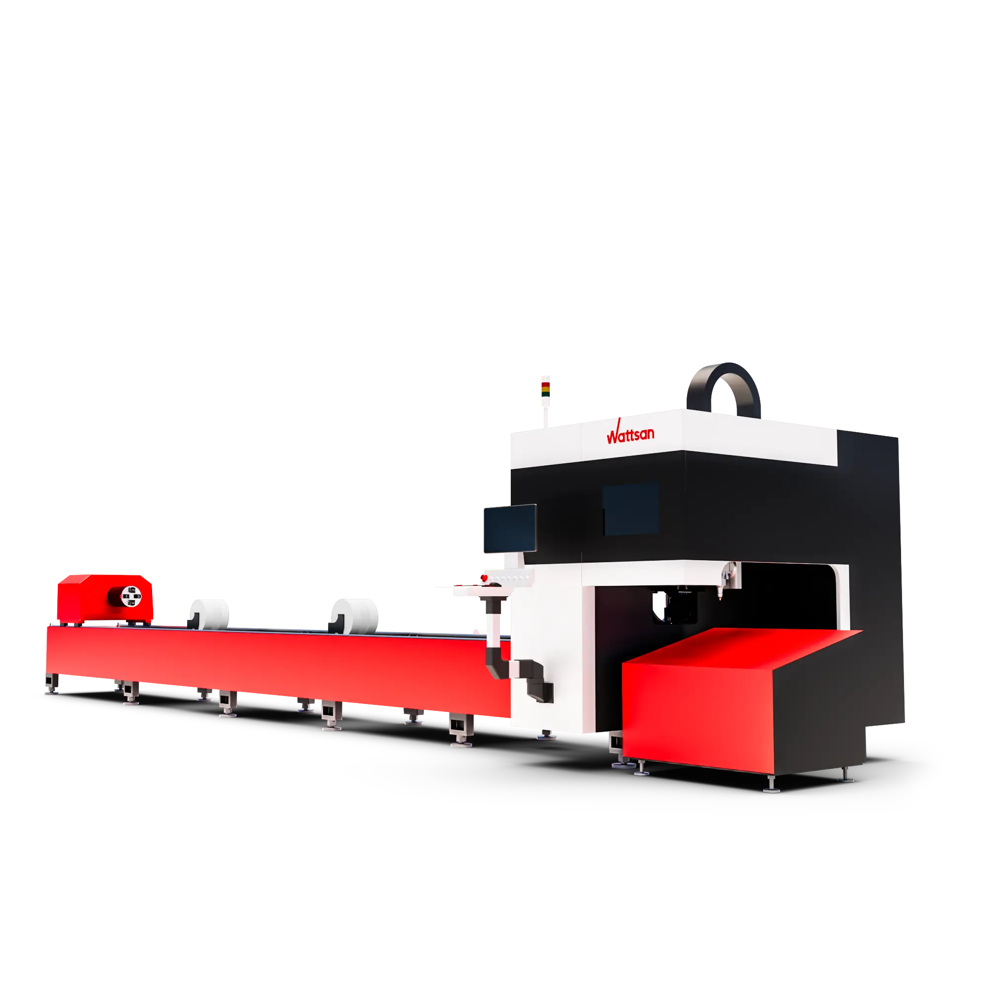
Fiber Laser Tube Cutting Machines
Tube cutting machines use a rotating chuck and dedicated tube or profile support to guide programmed cuts around a three-dimensional workpiece.
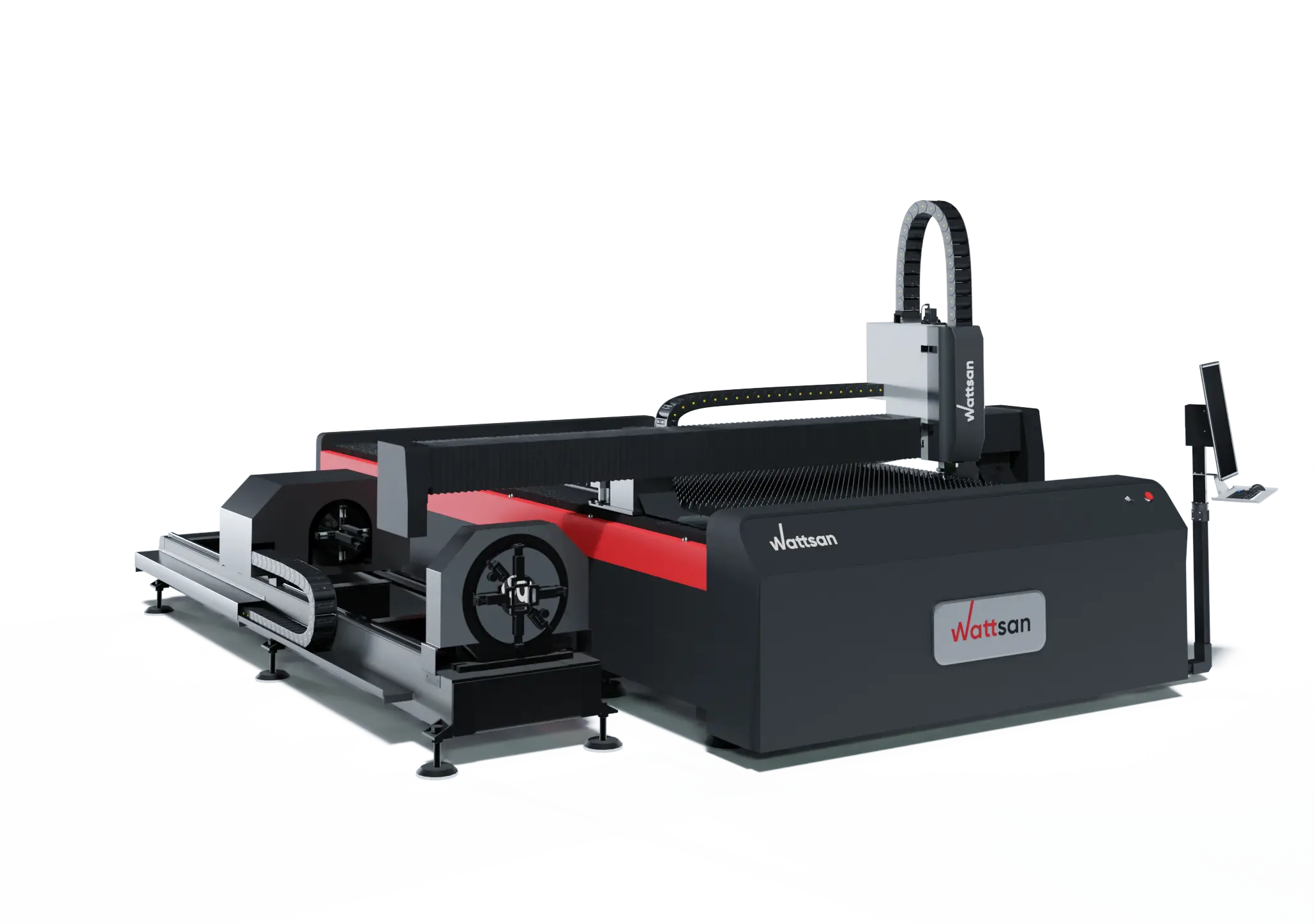
Sheet-and-Tube Combination Machines
Some platforms integrate flat-sheet and tube-processing capability on one machine, with configuration-specific trade-offs depending on production needs.
What Materials Can a Fiber Laser Cutting Machine Cut?
What can a fiber laser cut? In industrial cutting machines, the technology is used primarily for metals such as carbon steel, stainless steel, aluminium, copper, brass, and titanium. Exactly what materials a fiber laser can cut - and at what thickness, speed, and quality - depends on the complete machine and process configuration.
Being technically cuttable does not mean every machine can cut every grade or thickness at the same speed or quality. Capability depends on the source, beam characteristics, cutting head, assist gas, material condition, thickness, and validated process parameters. Selected coated metals and alloys can also be processed where the machine and process have been validated for that specific application.
Standard industrial ytterbium fiber cutters are metal-focused systems and are not typically used for cutting wood, acrylic, glass, fabric, plastics, or composites.
Advantages and Limitations of Fiber Laser Cutting Machines
| Advantage | Required qualification |
|---|---|
| Non-contact cutting | No cutting tool contacts the sheet, but consumables and machine parts still require maintenance |
| High speed on suitable metals | Speed depends on material, thickness, gas, geometry, and required edge quality |
| Narrow kerf and detailed contours | Minimum feature size and tolerance are not determined by spot size alone |
| Efficient fiber source | Whole-machine consumption also includes cooling, extraction, drives, controls, and gas production/supply |
| Processing of reflective metals is possible | Requires a compatible source, head, back-reflection protection, and validated parameters |
| CNC automation and repeatability | Reliable unattended production requires monitoring, automation, maintenance, and a stable process |
| Reduced open-beam alignment compared with traditional CO2 systems | Cutting-head optics, protective windows, nozzles, and mechanical systems still need inspection and service |
Fiber Laser Cutter vs. CO2 Laser Cutter
Fiber and CO2 laser cutting machines belong to different points in the main types of laser sources used in industrial machines, and the two architectures differ in gain medium, wavelength, and beam delivery.
| Feature | Fiber laser cutting machine | Traditional CO2 laser cutting machine |
|---|---|---|
| Common gain medium | Rare-earth-doped optical fiber | CO2-based gas mixture |
| Common industrial wavelength | Near 1 µm for ytterbium systems | Commonly around 10.6 µm |
| Beam delivery | Largely enclosed fiber delivery to downstream optics | Commonly free-space beam delivery using mirrors |
| Typical material focus | Metals | Non-metals and, in suitable high-power industrial systems, metals |
| Machine maintenance distinction | No long external mirror path to align in common designs | Mirror path and beam alignment are relevant in traditional designs |
CO2 lasers are not incapable of cutting metal - high-power industrial CO2 systems can and do cut metal. The limitation applies mainly to lower-power workshop CO2 machines, not to the technology as a whole. For the underlying mechanism, see how a CO2 laser works.
Does a Fiber Laser Cutting Machine Need Maintenance?
The sealed fiber laser source itself is largely low-maintenance, but that does not extend to the complete machine. Routine attention is typically needed for protective windows, nozzle condition and centring, cutting-head optics according to the manufacturer's procedure, chiller fluid and cooling system, assist-gas filtration and supply, extraction filters and ducting, worktable slats and collection areas, lubrication and motion components, and calibration, sensors, and safety interlocks.
Maintenance intervals vary by manufacturer and model - check the machine's own documentation rather than relying on generic figures such as a universal 100,000-hour service life.
Is a Fiber Laser Cutting Machine Safe?
The near-infrared beam used in fiber laser cutting is invisible but can cause severe eye and skin injury, and reflected radiation from metal can also be hazardous. Appropriate engineering controls are essential; depending on the machine configuration, these may include a protective enclosure, interlocks, beam containment, correctly rated viewing windows, or controlled-area access measures. Cutting fumes and particles require extraction, and coatings or unknown materials must be identified before processing. Hot material, sparks, and combustible contamination create fire risk, and servicing can expose hazards that are not present during normal operation.
Protective eyewear is not a generic item: where required, it must be selected for the specific wavelength, optical density, and task, and engineering controls take priority over personal protective equipment. The manufacturer's manual, operator training, a site-specific risk assessment, and applicable local regulations take priority over any general overview.
Conclusion
A fiber laser cutting machine turns a digital design into a finished metal part through a coordinated sequence of beam generation, delivery, focusing, piercing, gas-assisted melt removal, and CNC-controlled motion. Each subsystem depends on the others: a powerful source cannot compensate for a poorly aligned head, and precise optics cannot compensate for an unstable motion system.
Frequently Asked Questions About Fiber Laser Machines
Is a fiber laser the same as a fiber laser cutting machine?
No. A fiber laser is the source that generates the beam; a fiber laser cutting machine is the complete system - source, delivery fiber, cutting head, motion, and gas supply - that uses that beam to cut metal.
Does a fiber laser cutter melt or vaporise metal?
Primarily melts it. In most standard metal-cutting processes, melting followed by gas-assisted melt ejection is the dominant mechanism; partial vaporisation can also occur, but full vaporisation is not typical in everyday sheet-metal cutting.
Why does a fiber laser cutter need assist gas?
Assist gas physically ejects molten material from the kerf, which the laser alone cannot clear. Depending on the gas, it can also control or support edge oxidation and help stabilise the process.
What is the difference between oxygen and nitrogen laser cutting?
Oxygen reacts chemically with hot metal, adding energy through an exothermic reaction and leaving an oxidised edge; it is mainly used on carbon and mild steel. Nitrogen is largely inert, ejecting melt mechanically without reacting, which typically produces a clean, oxide-free edge on materials like stainless steel and aluminium.
Why does a fiber laser cutting head need autofocus?
Not every fiber laser cutting head includes or requires autofocus. Where provided, autofocus adjusts the beam's focus position without the operator manually repositioning the optical assembly, making it easier to switch between materials, thicknesses, and cutting processes. It does not optimise the job on its own; correct focus position still depends on validated parameters.
What is kerf in fiber laser cutting?
Kerf is the narrow channel formed when laser energy melts or removes material and assist gas clears it from the cutting path. Kerf width is influenced by beam spot size but is not identical to it, since gas flow, focus position, and material behaviour also affect the final channel width.
Can a fiber laser cutter cut copper and brass?
Yes, appropriately configured modern systems can. This requires a source and cutting head compatible with these highly reflective metals, adequate back-reflection protection, and validated parameters for the alloy and thickness.

